
FrameMaker Graphics
A video recording of this tutorial is available: video
Create or more FrameMaker documents in which you do the following steps.
Display the Graphics Toolbar
To get started creating graphics in FrameMaker, create a new document and display the Graphics toolbar:
- Open FrameMaker, and select File > New > Document > Portrait.

|
Note: For this exercise the Paragraph, Character and Table Designer toolbars will not be used. To clear the work area and create the most usable space in your document window, you may wish to reduce the size of the formatting toolbars. To minimize these toolbars, click the ►► symbol in the upper right-hand corner of the toolbars that will not be used. |
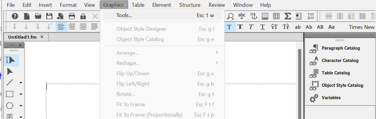
- Click View > Toolbars > Graphics Toolbar. The document window will appear as follows:
The Graphics toolbar will appear in the document window and
contains the following tools and properties:
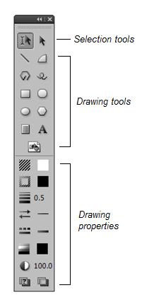 |
- Selection tools: used to select existing text and draw objects.
- Drawing tools: used to draw or insert shapes such as lines, arcs, rectangles,
circles, and polygons. Also, these tools allow the insertion of text boxes, free-hand drawing of shapes and the placement of graphic frames.
- Drawing properties: used to view and change an object's
properties, once it has been created.
|
You will use the Graphics toolbar to select drawing tools, create graphic objects and change the properties
of drawn objects.
- Select File > Save As.
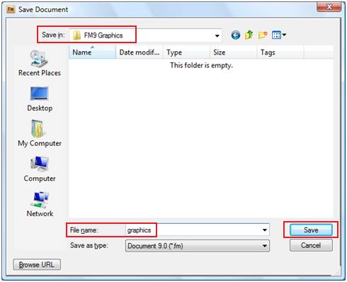
- In the File name box, type graphics, and click Save. The Save Document dialog box should appear as follows:
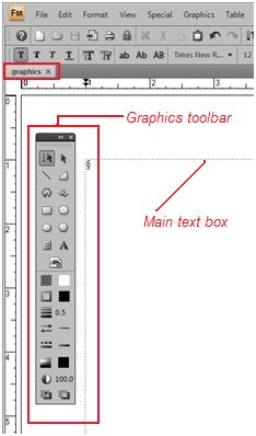
The new document window will appear with the Graphics toolbar in an easily accessible position. The new document window should appear as follows:
Draw Basic Shapes
For this tutorial, you will create some simple shapes using the drawing tools.
|
|
Note: Before you draw any graphics, create an anchored frame within which you draw all the objects in the following tutorial. For details, see anchored frames.
|
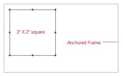
For this exercise, an anchored frame has been created with the following attributes:
- Anchor position: Below current line
- Alignment: Centered
- Width: 5" and Height: 3"
If you have created a similar anchored frame, the document window should appear similar to the following:
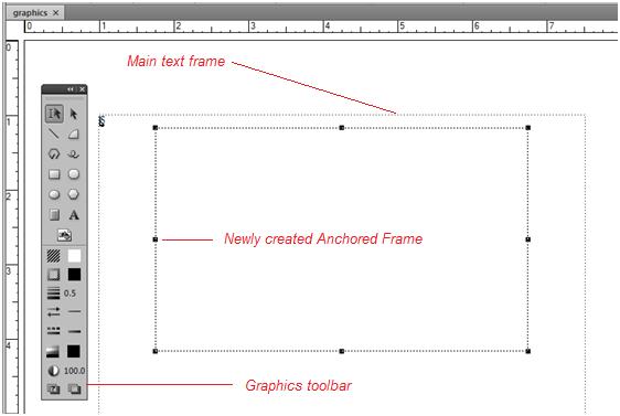
Notice that the document window displays the Graphics toolbar in a vertical format, along the left, just outside of the main text frame. By clicking on the black area at the top of the Graphics toolbar, the entire toolbar can be moved to any location on your screen.
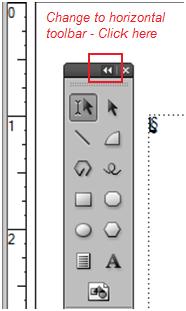
Click on the ◄◄ arrow symbols located at the top of the toolbar to change from a vertical appearance to a horizontal position. The Graphics toolbar should appear similar to the following:
The Graphics toolbar may be more accessible in a horizontal format for a specific task in FrameMaker. When changed to a horizontal format, the Graphics toolbar will appear as follows:
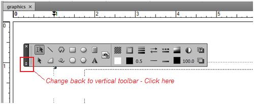
Click the arrow symbols to change the Graphics toolbar back to the vertical position.
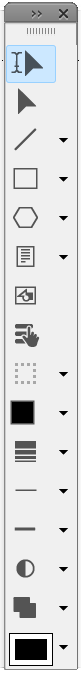
The Graphics toolbar contains the following drawing tools:
To draw a rectangle:
- On the Graphic toolbar, click on the Place a Rectangle icon.
- Click and drag the crosshair in the document window to draw a rectangle that is approximately 2 inches in width and 1-inch in height.
To make this measurment more precise, observe the lower left corner of the document window for the current measurments of your rectangle. As you move the crosshair symbol, the measurements in the left corner will change to reflect the new dimensions of the rectangle.
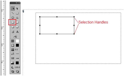
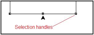
After you release the mouse button and move the pointer away from the rectangle,
a set of selection handles will appear on the edges on the rectangle. The rectangle should appear as follows:
|
|
Note: You use the same basic procedure to draw
circles, arcs, lines, and freehand lines. |
- Press the Delete key to delete the rectangle. Try other shapes to experiment with how the icons are used. Delete these shapes before proceeding.
To draw a square:
- On the Graphics toolbar, click on the Place a Rectangle icon.
- Press and hold the Shift key, and then drag the crosshair to create a square that measures approximately 1-inch in width by 1-inch in height. (Holding the Shift key keeps the sides of the rectangle equal, allowing
you to easily create a square.) You may check the exact dimensions of your square in the lower left corner of your document window, while dragging the crosshair.
- Select Graphics > Object Properties. The Object Properties dialog box will appear as follows:
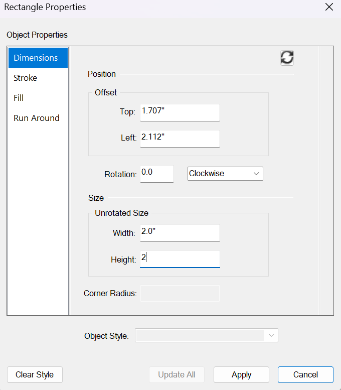
- In the Object Properties dialog box, type 2.0" in the Width and Height
boxes.
- Click Set. The Object Properties dialog box allows you to create objects using exact
measurements. The square now measures 2" by 2" and appears as follows:
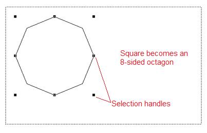
To draw an octagon:
- Select the square from the previous exercise.
- Select Graphics > Set # Sides. The Set Number of Sides dialog box will appear as follows:
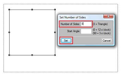
- In the Set Number of Sides dialog box, type 8 in the Number of Sides
box.
- Click Set.
The square changes to an octagon. The square (with 4 sides) is now changed to an octagon (with 8 sides.) The anchored frame should appear as follows:
- Click outside of the octagon once and the selection handles will disappear. Click on the border of the octagon and the selection handles appear again.
Select Objects
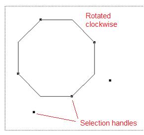
You can use the selection handles to resize, reshape or rotate a created object.
For example, to rotate the octagon you just created, select the border of the
octagon, press and hold the Alt key and the ↔ symbol appears. While the ↔ symbol is displayed, the object can be rotated clockwise or counter-clockwise. Drag a selection handle to rotate the octagon. For more information about resizing objects, see Resizing
Objects.
The octagon shown in this exercise has been rotated clockwise to appear as follows:
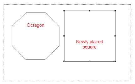
Align Objects
To align objects:
- In the existing anchored frame, draw a square that measures approximately 2 inches in width by 2 inches in height. (Remember to press and hold the Shift key to form a square.) The square should appear inside the anchored frame as follows:
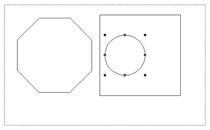
- Click the Place an Oval icon and draw a circle that measures approximately 1-inch, inside of the square. (Press and hold the Shift key to draw a circle.) The square will appear with the circle inside, as follows:
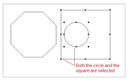
- With the circle still selected, press and hold the Shift key, and then select
the square. (Both objects should be selected and both sets of selection handles should be displayed.) The two objects will appear as follows:
- Select Graphics > Align.
- In the Align dialog box, select T/B Centers and L/R Centers. The Align dialog box will appear as follows:
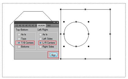
- Click Align.
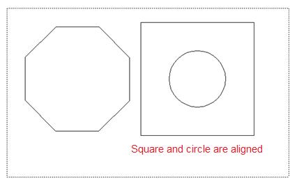
The circle is aligned in the center of the square. Click outside of the square and circle. The selection handles will disappear. The two objects will be aligned and appear as follows:
- Close the Align dialog box.
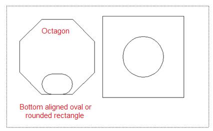
- To create an oval or rounded rectangle inside of the octagon, select Graphics > Align. In the Align dialog box, select Bottom and L/R Centers. Click Align. The octagon should appear as follows:
Resize Objects
To resize objects:
- Select the square that you created in the previous exercise.
- Position your cursor over the bottom-center selection handle until your
cursor changes to the
 arrow symbol.
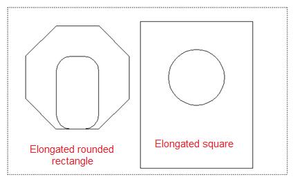
- Click the selection handle that has changed to the arrow symbol, and drag downward a few inches to extend the
square into a rectangle. Make sure to stay within the boundries of the anchored frame.
- Click the selection handles on the oval located within the octagon and extend the oval upward. The objects within the anchored frame will appear similar to the following:
|
|
Note: You can also resize an object to exact
measurements by right-clicking the object, selecting Object Properties,
and then typing exact measurement for Width and Heigth properties. |
- Select File > Save.
Duplicate Objects
To duplicate objects:
- Select the circle that you created in the previous exercise.
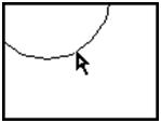
- Place your cursor inside of the circle.
Your cursor changes to the  hollow arrow symbol.
- Press and hold the Ctrl key, and then drag the circle downward.
Notice that the  plus sign symbol is added to your cursor.
This signifies that you are dragging
a copy of the object instead of the original object. You have created a second circle that is the same size as the first circle.

|
Caution:: FrameMaker will send a warning that your changes will not be able to be undone and that the Undo history will be lost. Press OK to continue.
|
cTo drag the object in a straight line,
press and hold the Shift key.
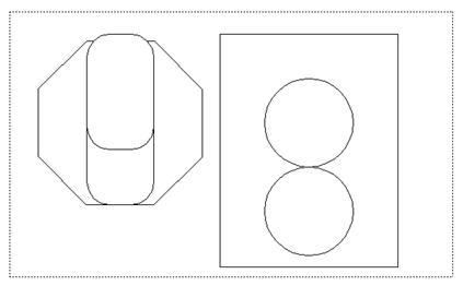
- Repeat the steps above to create a second rounded rectangle or oval in the octagon. A similar warning message will appear stating that your changes cannot be undone. Press OK to continue. The anchored frame will appear as follows:
- The remaining exercises in this assignment only involve the square and circles. Select the octagon and the inserted objects (rounded rectangles or ovals) and delete these items from the anchored frame.
- Select File > Save.
Distribute Objects
To evenly distribute objects:
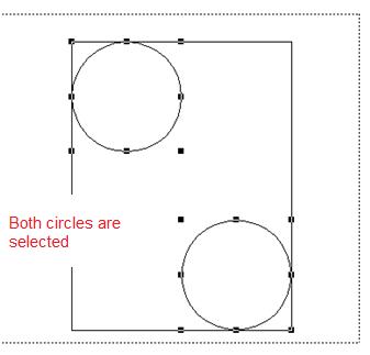
- Select one of the circles that you created in the previous exercise. Click inside of the circle and drag the circle to the upper left corner of the rectangle. Drag the other circle to the lower right corner of the rectangle.
- Press and hold the Shift key, and then select both of the circles. The rectangle with the two circles inside shoudl appear as follows:
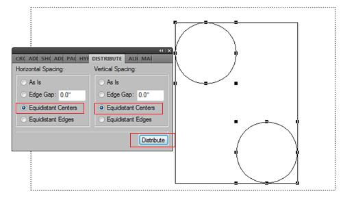
- Select Graphics > Distribute.
- In the Distribute dialog box, select Equidistant Centers for both
Horizontal Spacing and Vertical Spacing. The Distribute dialog box should appear as follows:
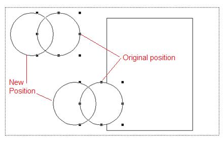
- Click Distribute. The two circles are now distributed with equal
space between them. They move as one unit and can be repositioned within the anchored frame. Because you have designated that these two circles are to remain equally distant from each other, when one circle is moved the other circle moves accordingly. Notice how the circles move to the left at the same time, as shown below:
Group Objects
To group objects:
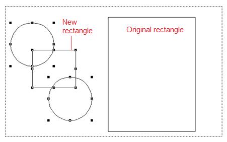
- Place a new rectangle within the anchored frame.
- Select the two circles and the new rectangle. The anchored frame should appear as follows:
- Select Graphics > Group.
The three objects (two circles and one small rectangle) are now grouped together and treated as one object. The
selection handles change to reflect this new grouping. The new grouping will appear as follows:
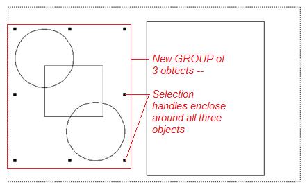
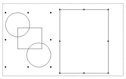
- With the group still selected, press and hold the Shift key, and then select
the original (larger) rectangle. The anchored frame will appear as follows:
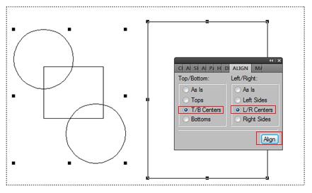
- Select Graphics > Align.
- In the Align dialog box, select T/B Centers and L/R Centers,
and click Align.
The Align dialog box will appear as follows:
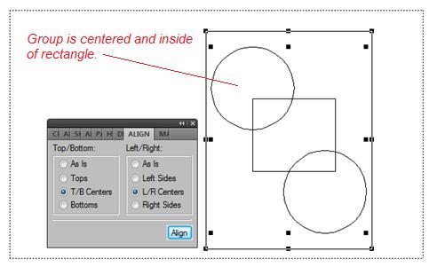
- Drag the align dialog box to the open area to the left of the two grouped objects.
The first group is now centered within the original rectangle, but FrameMaker still considers these to be two seperate objects. The group with the three smaller objects is laying over the top of the large rectangle. Each object still retains its own selection handles. The two objects will appear as follows:
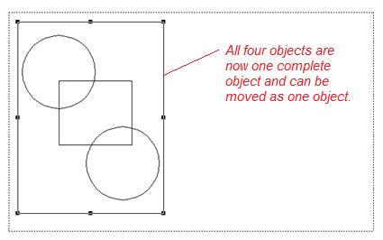
- With the selection handles of both objects showing, select Graphics > Group. The objects are combined in to one object and can be moved within the anchored frame as one object. The anchored frame should appear as follows:
- To ungroup the selection, select Graphics > Ungroup.
- Select File > Save.
Change Object Properties
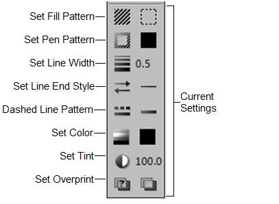
Using the Graphics toolbar, you can customize object properties such as color,
type of fill, and the line width of your object. The
left side of the Graphics toolbar contains the options for changing drawing properties,
and the right side displays the current settings.
To change object properties:
- All four objects should be ungrouped at this time. The four separate objects will include one small rectangle, one large rectangle, and two circles that are the same size.
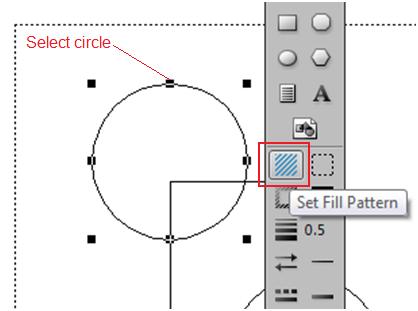
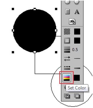
- Select the top circle.
- Click the
 Fill Pattern icon. The anchored frame should appear as follows:
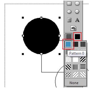
- In the Fill Pattern dialog box, select the solid fill option.
- Click the
 Set Color icon.
- In the Color dialog box, select Red.
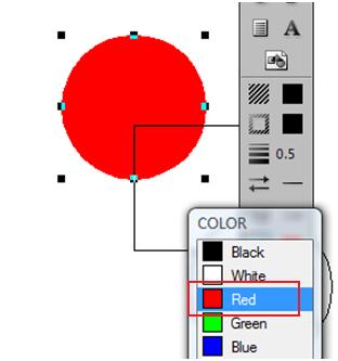
- Select the small rectangle in the middle of the two circles. Repeat the steps above to apply a solid, yellow
fill to the small rectangle.
- Select the lower circle, and apply a solid, green fill. The three graphic objects will appear as follows:
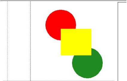
- Select the large rectangle on the left side of the anchored frame.
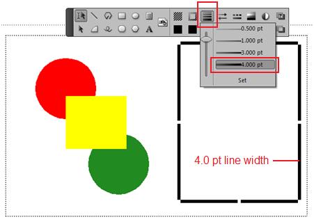
- Click the
 Set Line Width icon.
- In the Line Width drop-down menu, select a thick line weight. (For this example the 4.0 pt line width option has been chosen.)
Add Callouts and Text
Callouts and text are a common method of pointing to or describing a graphic item. These callouts direct the eye of the reader to additional information about the graphic.
To add callouts and text:
- Click the Set Line Width icon, and select a thinner line weight for the callouts.
- Click the
Set Color icon, and select the color black.
- Click the
 Place a Line icon. The graphic should appear as follows:
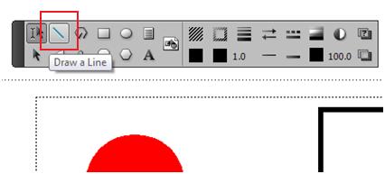
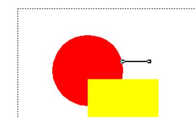
- Draw a line that extends out from the red circle. The red circle graphic should appear as follows:
|
|
Note: To create a horizontal line, press and
hold the Shift key. |
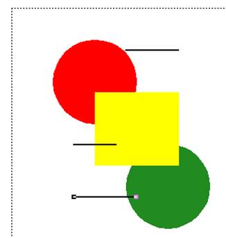
- Repeat the steps above to add a line to the yellow rectangle and the green circle. The three graphics should have callouts that appear similar to the following:
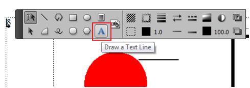
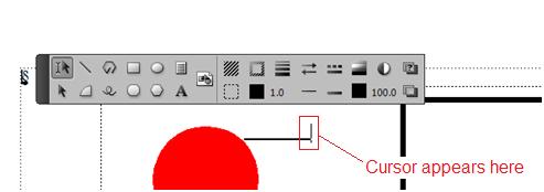
- Click the
 Draw a Text Line icon. The graphic should appear as follows:
- Click at the right end on the callout line for the red circle. A cursor will appear to display the position where the typed text will begin. The cursor will appear as follows:
- Type the word Red. (You can change the font and point size using
the Format menu.)
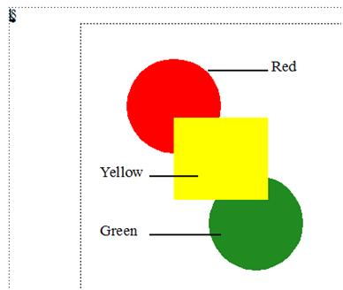
- Repeat the steps above to add text to the yellow and green circles. The three callouts with their accompanying text lines should appear similar to the following:
|
|
Note: Text lines are somewhat different than
other drawing objects because you can select the object (with selection
handles) or select the text characters. Experiment with the two types
of selection tools to see what kind of results you get. |
Apply and Customize Color
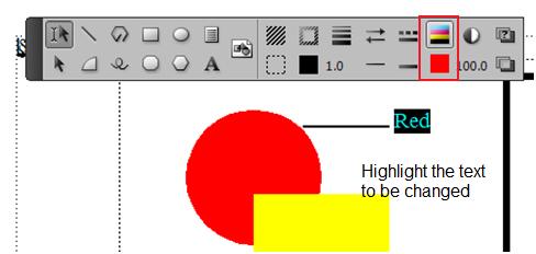
To apply color to text:
- Select some text and click the Set Color button on the Graphics toolbar.
- Select a color from the Color dialog box. The Graphics toolbar should appear similar to the following:
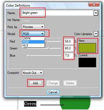
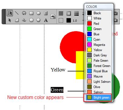
To customize a color, for example, a brighter green:
- Click View > Color > Definitions.
- Assign a name to your custom color. For example, type Bright green.
- For Model, select RGB.
- Push the red, green, and blue slider bars around until you get the shade of color you want.
The Color Definitions dialog box will appear as follows:
- Click Add.
Your customized color will be listed in the items under the Set Color button. The Custom Color list is updated and will appear as follows:
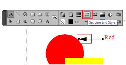
- Experiment with adding arrowheads to the callout lines to direct readers to the item described in your graphics. To do this, select the callout line, then click the Set Line End Style icon. Choose an arrow type and the arrowhead will be applied to your callout line. The line with an arrow attached to the end will appear appear as follows:
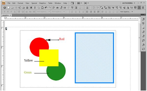
- Select the large rectangle in the anchored frame. Click the Set Fill Pattern icon.
- In the Fill Pattern dialog box, choose a fill pattern with a texture. Change the color of the textured fill pattern to a color of your choice.
- Select File > Save.
The completed graphics exercise should have an anchored frame filled with custom graphics that appear similar to the following:
In this tutorial you learned how to use the tools on the Graphics toolbar to create and draw graphic shapes, align and resize objects, apply fill color and texture, group and ungroup objects, modify customized colors and add callout lines and text to graphics. Experiment with the other
drawing tools and object properties.
Complete This Unit
Send your FrameMaker document(s) for this unit to your instructor at admin@mcmassociates.io (click this link)
Return
Return to your bookmarked course main page.
Related Information
Adobe FrameMaker Help Archive. PDF or HTML, 2019 appears to be the most recent edition. 900+ pages.
FrameMaker LinkedIn Group.. Have to request to join. Probably the best up-to-date info.
Adobe FrameMaker Classroom in a Book: https://www.amazon.com/dp/0137621108/. Not recommended.
Adobe FrameMaker. Promo page.
Information developed by Jill Brockmann, Jana Owens, Jacqueline J. Pulido, Thomas A. Moore, and David A. McMurrey. For information, contact admin@mcmassociates.io.